18 February 2016

Spiral Pipe for Offshore Application


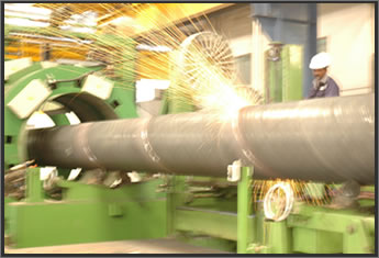
In certain parts of the world it is highly relevant to use spiral welded pipes for offshore applications. This is driven by cost, project characteristics and the desire to manufacture the pipe close to where it is to be used. Spiral welded line pipe has been used extensively for onshore applications, however there has been some reluctance to specify spiral welded line pipe for offshore applications. A joint industry project is beeing carried out together with coil manufacturers, pipe manufacturers, installation contractors and operators to review the status regarding offshore applications for spiral welded pipes and identify the most critical technology gaps using a technology qualification process. Detailed suggestions as to how the gaps can be met have been made. An update on efforts to close these gaps is ongoing. 

Spiral Pipe
Source : http://www.steelpipes.org/gavin/uploads/allimg/120313/16152U4a-0.jpg

The challenges for spiral welded line pipe include design, metallurgical and quality control issues. The design issues include fracture arrest, collapse and displacement controlled loading conditions which are all highlighted in DNVs standard for submarine pipelines (DNV OS F101). The design issues regarding load controlled displacement are mainly due to limited experience with spiral welded line pipe subjected to large strains. For running fracture the limited experience with spiral welded pipe for offshore applications is an issue.There are 5 new spiral welded pipe mills in United States so availability has improved. The review includes an assessment of typical pipe material test results and whether properties required for offshore applications can reasonably be expected.

 
Spiral Pipeline Manufacture
Source : http://azkafilardh.blogspot.co.id/2015/02/spiral-pipe-for-offshore-application.html


Det Norske Veritas (U.S.A.), Inc. (DNV) and MCSKenny are carrying out a joint industry project (JIP) to investigate the suitability of spiral welded pipe for offshore applications. It appears that the industry has a general understanding that the performance of spiral welded (SAWH) pipes is different to Submerge Arc Welded (SAWL)/ High Frequency Welded(HFI)/ Electric Resistance Welded ERW linepipe when exposed to the same loading conditions, and that currently existing design standards for offshore applications may not be applicable. An important issue is to establish how the spiral wound linepipe can be produced consistently to a high level of quality, and what is required by the design standard for spiral welded pipe to be fit for purpose for offshore use. Some of the main areas of concern regarding the quality of spiral wound linepipe will be discussed. The aim is to assess whether SAWH linepipe can be considered equivalent to SAWL and HFI/ERW linepipe. The use of spiral welded linepipe (SAWH) for pipelines has generally been the most popular manufacturing choice of linepipe for onshore low pressure pipelines, pipelines transporting water, ship borne piping, or very shallow water, low pressure pipelines (≤ 500 ft).
Recently there has been more interest in the use of spiral wound linepipe, due to the following reasons:
  • There are five new SAWH pipe mills in America with “state-of-the-art” technology.
  • SAWH linepipe is a cost-effective solution compared to the other manufacturing processes.
  • Generally, the chemical compositions, mechanical properties and dimensional tolerances are assumed to be comparable to SAWL pipe.
  • SAWH linepipe can be manufactured in 80 ft lengths with diameters from 20 to more than 100-inch OD and wall thicknesses ranging from approximately 9 to 25 mm.
  • Some SAWH pipe mills have coating capabilities for 80 ft pipe lengths (FBE and 3-layer coating systems). 80 ft pipe lengths could mean less fabrication costs for the installation contractors.


References : 
http://azkafilardh.blogspot.co.id/2015/02/spiral-pipe-for-offshore-application.html
Spiral Wound Linepipe for Offshore Applications G. Heiberg, Det Norske Veritas, A. Eltaher, MCSKenny, P. Sharma, Det Norske Veritas, P. Jukes, MCSKenny, M. Viteri Det Norske Veritas

Dega Damara Aditramulyadi
Student ID : 15512046
Course      : KL4220 Subsea Pipeline
Lecturer   : Prof. Ir. Ricky Lukman Tawekal, MSE, Ph. D.
                  Eko Charnius Ilman, ST, MT
Ocean Engineering Program, Institut Teknologi Bandung

Flexible Riser


Conduits to transfer materials from the seafloor to production and drilling facilities atop the water's surface, as well as from the facility to the seafloor, subsea risers are a type of pipeline developed for this type of vertical transportation. Whether serving as production or import/export vehicles, risers are the connection between the subsea field developments and production and drilling facilities.

Similar to pipelines or flowlines, risers transport produced hydrocarbons, as well as production materials, such as injection fluids, control fluids and gas lift. Usually insulated to withstand seafloor temperatures, risers can be either rigid or flexible.

Types Of Risers

There are a number of types of risers, including attached risers, pull tube risers, steel catenary risers, top-tensioned risers, riser towers and flexible riser configurations, as well as drilling risers.
The first type of riser to be developed, attached risers are deployed on fixed platforms, compliant towers and concrete gravity structures. Attached risers are clamped to the side of the fixed facilities, connecting the seabed to the production facility above. Usually fabricated in sections, the riser section closest to the seafloor is joined with a flowline or export pipeline, and clamped to the side of the facility. The next sections rise up the side of the facility, until the top riser section is joined with the processing equipment atop the facility.
Also used on fixed structures, pull tube risers are pipelines or flowlines that are threaded up the center of the facility. For pull tube risers, a pull tube with a diameter wider than the riser is preinstalled on the facility. Then, a wire rope is attached to a pipeline or flowline on the seafloor. The line is then pulled through the pull tube to the topsides, bringing the pipe along with it.
Building on the catenary equation that has helped to create bridges across the world, steel catenary risers use this curve theory, as well. Used to connect the seafloor to production facilities above, as well as connect two floating production platforms, steel catenary risers are common on TLPs, FPSOs and spars, as well as fixed structures, compliant towers and gravity structures. While this curved riser can withstand some motion, excessive movement can cause problems.


 Multiple Riser Configurations
Source : http://www.atlantia.com/seastar/

Used on TLPs and spars, top-tensioned risers are a completely vertical riser system that terminates directly below the facility. Although moored, these floating facilities are able to move laterally with the wind and waves. Because the rigid risers are also fixed to the seafloor, vertical displacement occurs between the top of the riser and its connection point on the facility. There are two solutions for this issue. A motion compensator can be included in the top-tensioning riser system that keeps constant tension on the riser by expanding and contracting with the movements of the facility. Also, buoyancy cans, can be deployed around the outside of the riser to keep it afloat. Then the top of the rigid vertical top-tensioned riser is connected to the facility by flexible pipe, which is better able to accommodate the movements of the facility.

Top-Tensioned Risers
Source : http://www.atlantia.com/seastar/images/scenarios_wettree2.jpg

First used offshore Angola at Total's Girassol project, riser towers were built to lift the risers the considerable height to reach the FPSO on the water's surface. Ideal for ultra-deepwater environments, this riser design incorporates a steel column tower that reaches almost to the surface of the water, and this tower is topped with a massive buoyancy tank. The risers are located inside the tower, spanning the distance from the seafloor to the top of the tower and the buoyancy tanks. The buoyancy of the tanks keeps the risers tensioned in place. Flexible risers are then connected to the vertical risers and ultimately to the facility above.

Hybrid Riser System
Source : http://www.2hoffshore.com/riser_engineering/freestanding.php

A hybrid that can accommodate a number of different situations, flexible risers can withstand both vertical and horizontal movement, making them ideal for use with floating facilities. This flexible pipe was originally used to connect production equipment aboard a floating facility to production and export risers, but now it is found as a primary riser solution as well. There are a number of configurations for flexible risers, including the steep S and lazy S that utilize anchored buoyancy modules, as well as the steep wave and lazy wave that incorporates buoyancy modules.
While production and import/export risers transfer hydrocarbons and production materials during the production phase of development; drilling risers transfer mud to the surface during drilling activities. Connected to the subsea BOP stack at the bottom and the rig at the top, drilling risers temporarily connect the wellbore to the surface to ensure drilling fluids to not leak into the water.

Reference :
http://www.rigzone.com/training/insight.asp?insight_id=308&c_id=17

Dega Damara Aditramulyadi
Student ID : 15512046
Course      : KL4220 Subsea Pipeline
Lecturer   : Prof. Ir. Ricky Lukman Tawekal, MSE, Ph. D.
                  Eko Charnius Ilman, ST, MT
Ocean Engineering Program, Institut Teknologi Bandung

Pipeline Free Span Mitigation

Pipelines installed in marine environments for transportation of oil and gas from the offshore platforms has become “lifelines” of the oil industry. The water depths in which these pipelines are laid may vary from tens of meters to hundreds of meters. These offshore pipelines can be laid on the sea bed surface, they can be buried, or they can be trenched. When the pipelines are laid in the sea, they are exposed to direct flow of sea water .

Scour Caused by Span
Source : https://edarikahiki.files.wordpress.com/2013/02/118-15.jpg

This causes scour around the pipeline, which leads to suspended free spans of the pipe line. The pipeline along the length of the suspended span may or may not sag in the generated scour hole. In case of a sagging pipeline, the pipeline may reach the bottom of the scour hole, which is followed by backfilling which eventually lead s to self – burial of the pipeline.

If free-spans are long, the vortex induced vibrations (VIV) can cause the pipeline to undergo fatigue damage and severely reduce the pipeline design life.

Underwater pipeline protection is of major concern for the Oil and Gas operating companies. They carry high pressure crude oil, gas, and products and hence their health is of major concern. Given the amount of threat present in the underwater pipeline, the following protection :

Rock and Gravel Dumping

Rock and gravel dumping provides a protective layer of rip- rap around the pipeline. Various installation techniques have been employed from the surface vessels, namely:
From a side- dumping barge or vessel with individual stones falling to the sea bed, From a split- hopper barge as one big mass, From a barge through a pipe to reduce the fall velocity of the rock and improve placement accuracy.


Rock and Gravel Dumping

Source : http://www.nordnes.nl/rockinstallation/freespan_correction.jpg

The type of material req uired and the amount of material required is determined by the site location and hence the method of deployment depends on it. The material used to form the protective layer must offer sufficient resistance to withstand the flow induced forces (enhanced sh ear stress, vortex action). The stability of the local sea bed material can be calculated based upon knowledge of the local flow field around the pipeline.

Mattresses

Prefabricated mattresses have been used in bed protection or preparation schemes. These mattresses can be installed in a controlled manner as compared to the rock dumping method. Mattresses are often used to provide the much needed protection to pipelines but it can also be adopted for other sea bed structures. One of the major advantages of using mattresses is that they are flexible and can be laid to suite the local bed contours. 

Mattresses
Source : http://www.formshore.com/images/pipeline-pyramid-img1.jpg

The various types of protective mattress used for pipeline protection are: 
• Fascine mattress: it synthetic filter fabric strengthened with synthetic or natural fascines, 
usually overlain by rock dump material 
• Block mattress – it continuous array of concrete blocks held together by cables and laid on the sea bed or individual blocks held in it pattern on the sea bed by synthetic nails 
• Cell mattress — mesh baskets filled with sand or gravel, large rocks in large wire mesh also called gabion baskets 
• Concrete mattress – the mesh baskets of the cell mattress are filled with underwater concrete instead of ballast 
• Stone asphalt mattress – a synthetic filter fabric ballasted with it stone and asphalt mixture 
• Ballast mattress — a heavy synthetic fibres woven mattress is double folded at both sides and tilled with sand or gravel.


Whilst the rock rip- rap is held in place due to its own weight and resistance between the rock and the underlying layers. The mattresses are often held in place by the use of soil pins or anc hors.
The resistance to pull out presented by the soil fixings, or the tensile strength of the material joining the mattress to the anchor, is designed to resist the uplift and drag due to hydrodynamic forces. Poorly designed fixings have historically been the most common cause of failure of these types of protection devices. Steps are often taken to fill any unevenness in the bed beneath the structure and this provides additional protection 
from scour.


Trenching (Pipelines) Or Increasing Structure 

Embedment Trenching of pipeline or increasing the structure embedment in the sea bed provides the much needed sheltering from wave and current forces which cause scour. This increases the pipeline stability and also the margin of safety against the undermining by scour as a result of greater soil-structure interaction.The trenching of pipeline into the sea bed not only provides protection from the scour activity but it also reduces the hydrodynamic load on the pipeline thereby adding stability to it. The increased embedment of the pipeline results in reduced flow fields around it when compared to pipeline resting on initial bed level. When trenching or increased embedment of pipelines are not feasible in harsh environmental conditions it may be necessary to stabilize them with anchors. 
In a region of active sediment movement or sand waves, sea bed needs to be ploughed flat prior to the installation. This causes the sand waves to reform and migrate over the pipeline resulting in changes to the pipeline cover over time, thereby providing cheap and effective way of protecting and stabilizing a pipeline. The embedment process can be enhanced with the use of a spoiler placed along the top of the pipe.

Sumber :
https://anggraenieka.wordpress.com/2014/01/30/pipeline-free-span-mitigation/

(www.ijert.org%2Fbrowse%2Fmay-2012-edition%3Fdownload%3D45%253Ascour-mechanism-detection-and-mitigation-for-subsea-pipeline-integrity%26start%3D10&ei=QiANUbuKGsytrAeXxYHgCQ&usg=AFQjCNEiFAjXiCF7mwSAik3AcPbyY_EhXg&bvm=bv.41867550,d.bmk&cad=rja)

Dega Damara Aditramulyadi
Student ID : 15512046
Course      : KL4220 Subsea Pipeline
Lecturer   : Prof. Ir. Ricky Lukman Tawekal, MSE, Ph. D.
                  Eko Charnius Ilman, ST, MT
Ocean Engineering Program, Institut Teknologi Bandung

Pig Launcher

PIG
PIG’s are devices that are inserted into pipelines and used to clean, inspect, or maintain the pipeline as they pass through it. They may also be used to separate different batches or types of product within the pipeline. For effective movement through the pipeline they are usually cylindrical or spherical and may be bullet shaped.

PIG
Source : http://www.cleaningwork.co.kr/Eng/clean/images/pig-big-1.jpg

PIG’s were traditionally used in the oil industry for large diameter pipelines. However, because of their useful qualities and the benefits they bring to pipelines, they have begun to be used in a very broad range of pipelines from small to large diameter. Nowadays they are also by no means found only in the oil and gas industry; they can be found in use at many plants and industrial sites and are effective just about anywhere a pipeline is in use. For example PIGs and PIG systems may be found in operation at plants and factories that process lubricating oils, toiletries, paints, a host of different chemicals, consumer cosmetics, and even foodstuffs.The earliest PIGs were likely made of straw and wrapped in wire to facilitate pipe cleaning. Conventional wisdom holds that it was from this early use that PIGs get their name since the squealing sounds they made as they passed through the pipes reminded people of the sounds a pig makes. The industry term PIG is likely a backronym and it is generally explained to mean ‘Pipeline Inspection Gauge;’ however, some people also use it to mean’ Pipeline Intervention Gadget.’

PIG Launchers and PIG Receivers
In simplest terms the PIG launchers and PIG receivers are the sections of the pipeline which allow the PIG to enter and exit the pipeline. They are generally funnel, Y-shaped sections of the pipe which can be pressurized or depressurized and then safely opened to insert or remove PIGs. Most pigging systems use bidirectional launchers and receivers that can work in either direction. This is important to allow the PIG to be retrieved by the launcher if there is a blockage in the pipeline which prevents it from reaching the receiver.
PIG launchers and receivers come with safety valves and locking system to prevent accidents. They are also optimized to be suitable to the pressure and temperature requirements of the pipeline. Launchers and receivers may be horizontal or vertical depending on the needs of the pipeline.

Source : http://www.cleaningwork.co.kr/Eng/clean/image/12_2.jpg

Some launchers are designed to hold multiple PIGs at once and configured to launch them according to preset conditions. This is very useful because it allows much of the work to be done remotely. Additionally it prevents the launcher from having to be depressurized and repressurized again each time a single PIG is needed. It is the pressure from the flow of product that moves the PIGs through the pipeline. Thus one of the main roles of launchers and receivers is to safely interface between the low-pressure outside world and the high-pressure pipeline.

Prosedure Launching and Recieving
The exact procedure for operating a PIG launcher or PIG receiver will vary somewhat depending on the particular pigging system being used. However, for the most part it will include the following steps:

LAUNCHER:
§  Pipeline operator should make sure that the isolation valve and kicker valve are closed.§  If the system is a liquid system then the drain valve and vent valve should then be opened to allow air to displace the liquid; if the system is a gas system then the vent should be opened so that the launcher reaches atmospheric pressure.
§  After the PIG launcher is completely drained to 0 psi, with the vent and drain valves still open, the trap door should then be opened.
§  The PIG should then be loaded with its nose in contact with the reducer.
§  Closure seals and other sealing surfaces should be cleaned and lubricated as needed and then the trap door should be closed and secured.
§  The drain valve is then closed and the trap is slowly filled by gradually opening the kicker valve.
§  Once filling is complete the vent valve is closed so that the pressure will equalize across the isolation valve.
§  The isolation valve is then opened and the PIG is ready for launching.
§  Next the main valve is gradually closed, increasing the flow through the kicker and behind the PIG until finally the PIG leaves trap altogether and enters the pipeline itself.
§  After the PIG leaves the launcher the mainline valve is fully opened and the isolation valve and kicker valve are closed.

RECEIVER:
§  The receiver should be pressurized.§  The bypass valve should be fully opened.
§  The isolation valve should be fully opened and the mainline valve partially closed.
§  Once the PIG arrives the isolation and bypass valves should be closed.
§  The drain valve and vent valve are then opened.
§  Once the trap is fully depressurized to 0 psi the trap can be opened and the PIG removed.
§  The closure seal and other sealing surfaces should be cleaned and lubricated as needed and the trap door should then be re-shut and secured.
§  The receiver should then be repressurized and returned to its original condition.
These processes may differ somewhat on different systems and of course if the launcher will be launching multiple PIGs then they should all be loaded at the loading stage.

References : 
http://setxind.com/midstream/what-are-pig-launchers-and-receivers/. January 2015

Dega Damara Aditramulyadi
Student ID : 15512046
Course      : KL4220 Subsea Pipeline
Lecturer   : Prof. Ir. Ricky Lukman Tawekal, MSE, Ph. D.
                  Eko Charnius Ilman, ST, MT
Ocean Engineering Program, Institut Teknologi Bandung
http://www.ocean.itb.ac.id/en/ 

Offshore Pipeline Route Selection (Pipeline Routing)


Planning and designing are the first things to do before installing offshore pipeline system. Before the pipeline design is made, a series of surveys is done to determine the best plan (the safest, the cheapest, the most environmental friendly) for the pipeline project. One aspect of planning that impacts a pipeline project from beginning to end, is it’s route selection.
In the planning stage, there is one key component that all pipeline projects have in common-how the initial routing of the pipeline will affect the eventual interface of all activities required for the project.
Pipeline route selection or routing is choosing the best route or path for the pipeline system to be outstretched toward the existing bathymetry and platform location. There are some criteria to be considered in routing, such as:
  • The safest
  • The shortest
  • The easiest to install
  • The minimum cost
The Safest
Safety first. That would probably be the most crucial thing in the whole process of producing the pipeline system. The safest route should be considered due to its minimum risk and impact for human and for the existing environmental surround. Moreover, existing landscape should be taken into account. Troughs, volcanoes, scarps, faults, and other extreme landscape (including geohazard) should be avoided in selecting the pipeline route.

The Shortest
The shortest means the most efficient and effective route. Minimum material will be needed, minimum pressure loss, as well as minimizing installation risk. Please note that longer pipeline will be more susceptible to pressure loss. If long pipeline route shall be installed, then putting some additional compressor along will be necessary.

The Easiest to Install
As told before, installing offshore pipeline system is not an easy task. Therefore we should manage the simplest way to install them offshore.

The Minimum Cost
If the three criteria mentioned before is obeyed, then it’s possible to have the minimum cost all the way.


Example Case of Pipeline Routing Selection 
Source : Slide KL4200 Subsea Pipeline


References :

Dega Damara Aditramulyadi
Student ID : 15512046
Course      : KL4220 Subsea Pipeline
Lecturer   : Prof. Ir. Ricky Lukman Tawekal, MSE, Ph. D.
                  Eko Charnius Ilman, ST, MT
Ocean Engineering Program, Institut Teknologi Bandung

Offshore Pipeline Installation


Offshore pipeline installation is the next step after designing. These days, there are few methods that commonly used and can be adapted to install offshore pipeline system, such as S-Lay method, J-Lay method, O-Lay method, Reel Lay method, and Beach Pull.

S-Lay Method

This method is quiet time-saving and can be done in vary depths. S-Lay refers to the pipeline shape forming “S” during the installation. This method requires lay-barge or other vessel designed to pipe-laying. Pipe is eased off the stern of the vessel as the boat moves forward. The pipe curves downward from the stern through the water until it reaches the seafloor. As more pipe is welded in the line and eased off the boat, the pipe forms the shape of an “S” in the water. Stingers, measuring up to 91 meters long, extend from the stern to support the pipe as it is moved into the water, as well as control the curvature of the installation. Some pipe-lay barges have adjustable stingers, which can be shortened or lengthened according to the water depth.

In S-Lay method, pipe receive more stress, especially at the bending (curve). This may become a concern due to pipe-cracking.
S-Lay Method Schematic
Source : https://anakkelautan.files.wordpress.com/2014/01/32.jpg

S-Lay Barge
Source : https://oilandgastechnologies.files.wordpress.com/2012/09/s-lay.png


J-Lay Method

J-Lay method put less stress on the pipe during installation, since there are only one bend (curve) forming the shape of “J”. This method inserts the pipeline in an almost vertical position. Pipe is lifted by a tall tower on the boat/barge, then inserted into the sea. The pipe bends once, under the water, taking on the shape of “J”.

J-Lay Method Schematic 
Source : https://blogger.googleusercontent.com/img/b/R29vZ2xl/AVvXsEhB36sUGbmDegfkiV4TJvXAuyEAtAWEUSmQ2gwgzha2xINomMSNheNBgIcuPjCd2nPZUkCQoyhdpDLhztS9Nhe7Bw-pNxvUv6t-MzxK9YyMMpy4xH6jb9YR7t27KjVn83OyrtDexsMuZDnS/s400/3.jpg

J-Lay Barge
Source : http://www.wermac.org/nordstream/ns_images/nordstream36.jpg

O-Lay Method

By using the O-lay technology operational production costs can be reduced compared to the existing general methods of pipe laying offshore. With O-lay, the pipe laying operations will be faster than other methods used today. Pipe line installation of larger diameter pipe can be as fast as 25 km per day. Furthermore the technology is safer because there are less people working in the offshore environment and the offshore operations are done in a shorter period of time.
The bottleneck of welding and testing on the traditional lay-barge is not a procedure that is part of the installation process anymore. Welding and testing are done on an onshore construction site.

O-Lay Method Schematic
Source : http://www.o-lay.net/images/o-lay-PIJPNAAR_BODEM_lang.jpg

Reel Lay Method

This method is firstly proposed to install pipeline with relatively small in diameter. But it have been developed to install pipeline with 12″ to  16″ diameter in size. This method used coiled pipe on a spool (reel) resulting in fast productivity due to the ability to lay the pipe by “unwinding” it from the reel. The process costs due to the reduced number of personnel required to lay the pipe, lowering the risk of accidents at the same time, and providing efficiency in the availability of the pipe.
Each reel is designed to operate with a specific barge and can usually handle pipe from 2″ to 12″. The total length capacity depends on the spool dimensions and the diameter of the pipe.

 
Reel-Lay Method Schematic
Source : http://www.tomarine.com/images/Reel-Lay-01.png

Reel Lay Barge
Source : http://www.offshore-mag.com/content/dam/offshore/print-articles/Volume%2072/sept/bond1-1209off.jpg

Beach Pull Method

Beach pull or also known as shore pull method is adapted for a near-shore pipe installation that is perpendicular to the shoreline, with pulling pipeline from the shore. Pipe is welded on a lay barge where the end of the pipe to shore set with pull head. Pull head hooks cable from shore.
The cable is connected to a winch on shore. Pulled pipe then glided into water through its route. Each segment of pipe is completed with buoy. When all pipes are on they’re position, buoys then being released.


Beach Pull Schematic
Source : Slide KL4200 Subsea Pipeline


Beach Pull Method 
Source : https://encrypted-tbn2.gstatic.com/images?q=tbn:ANd9GcQW75xUwCnKfrgPykHWPxuj_kLV3dJrYjVgKnFeSfTNLBBmUCFk


References:
Santika, Anindya Rizki. Laporan tugas akhir: Desain dan Analisis Instalasi Pipa Bawah Laut Menggunakan DNV OS F101 2010 dan DNV 1981. Bandung. 2011.
https://nonerieska.wordpress.com/2013/01/30/offshore-pipeline-installation/
http://www.o-lay.net/

Dega Damara Aditramulyadi
Student ID : 15512046
Course      : KL4220 Subsea Pipeline
Lecturer   : Prof. Ir. Ricky Lukman Tawekal, MSE, Ph. D.
                  Eko Charnius Ilman, ST, MT
Ocean Engineering Program, Institut Teknologi Bandung